no more available
For controlling the receivers, transmitters and antennas of a complex automatic satellite amateur radio station, a simple and low-cost remote control system would be useful.
We defined a bus system, called SHACKBUS.
Some key assemblies to build a flexible amateur satellite transceiver system are under development and will be available in mid 2001.
| Simple and lowest cost interface to all brands of controllers: Windows, Mac, OS/2, Linux, DOS, BASIC, C, PIC, MCU etc. | |
| Many devices can be controlled by one controller via a single 3-wire bus. | |
| Absolutely open protocol, anyone should be able to write control software | |
| Anyone should be able to make new devices to be controlled via the SHACKBUS, using a small PIC-controller or similar. | |
| Devices must not send data unless polled by the controller to simplify controller software and hardware. | |
| No speed required, no restrictions for length of bus wires. |
| Serial (RS232) based system: No extra PC card required. No drivers to
load. Can be used with all brands and operating systems, including smallest PIC and other MCU. Slow speed (9600 baud), no simultaneous transmit and receive operations. | |
| Choice to use USB instead of RS232 if the controller hardware and
system supports USB. Internal communication between SHACKBUS-Interface and devices however uses 9600 baud serial. | |
| Every device attached to the bus has its own unique address. | |
| The command lines start with the device adress and ends with <CR>. |
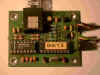
 (click to enlarge)
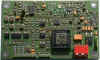
| SHACKBUS uses 3 wires. Voltage level is 5 Volt (idle) and 0 Volt (data): BUSIN (controller to all devices): normal TTL level signal BUSOUT (devices to controller): TTL open collector signal with pullup BUSGND (common ground wire) | |
| Data from 'PC' controller (RS232) is converted to the BUSIN line using a simple MAX232 receiver with TTL output. | |
| The BUSOUT wire is a 'wired or' line with a pullup resistor. The devices use a open collector npn-transistor or just a diode to output the replies to the controller. Data to PC is converted using a single MAX232 transmitter. |
The SHACKBUS protocol is simple and clear:
| Every valid command line consists of four parts: 1. One Asterisk (* = h2A) as first character, marking the beginning of a command string. 2. Two address Bytes (Uppercase and figures only) 3. a command string (variable syntax and length) 4. a RETURN character (<CR> = h0D) | |
| Commands are passed parallel to all devices, but only the one device which matches both address bytes will react and respond. |
There are some rules which have to be observed for proper operation of the SHACKBUS:
| Every device adress must be unique within one bus system. | |
| Devices must not access the bus without being individually adressed / polled by the controller (PC). | |
| If a device is properly adressed, it must react within 1 second after the
controller terminates the command and reply. ANY commands with the matching adress must be acknowledged - at least by sending an error message. |
Setting the receiver frequency to a PLL oscillator
command string (PC to PLL): *P1VO=00435450000 <CR>
| * is the start character for the SHACKBUS command | |
| P1 is the device address (user defined, e.g. P1 means 'PLL-oscillator No. 1) | |
| VO=* is the command "set receiver frequency" which will be interpreted by PLL processor | |
| 00435450000 is the desired frequency (in Hz) to be set by the PLL processor. |
The PLL must reply anything, e.g. *P1VO=00435450000 <CR>
Requesting the signal strength of a receiver
command string (PC to RX): *R3SS <CR>
| * is the start character for the SHACKBUS command | |
| R3 is the device address (user defined, e.g. R3 means 'Receiver No. 3) | |
| SS is the command "request signal strength value" which will be interpreted by receiver's processor |
The receiver will reply e.g. *R3SS=084 <CR> if the signal strength is -84 dBm signal
More command examples
*C1SR=4 Relay-driver
1 will set relay No. 4 (ON)
*C1CR=4 Relay-driver
1 will clear relay No. 4 (OFF)
*A1AZ=180 Antenna
azimuth is set to 180 degree
*A1EL=039 Antenna
elevation is set to 39 degree
*A1CA
Request current value of antenna azimuth (while running). Reply is: *A1CA=166
*A1ST
Request antenna rotor status. Reply is: *A1ST=0
(means 'final position reached')
There exists already some devices which use the SHACKBUS interface:
| A simple RS232 to SHACKBUS adapter with MAX232 and a bus timeout watchdog | |
| PLL programmable precision synthesizer (available in versions from 100 to
1300 MHz) setting of frequency, programming temperature compensation, offset calculation etc. | |
| MUX output device to control 8 outputs (relay, etc.) | |
| URX Universal receiver for 50 to 200 MHz (normally used with a
downconverter and PLL S-meter and Frequency offset (AFC) readout, switching of 4 different IF filters etc. |
However, we are just beginning to bring these assemblies to the amateurs.
We expect the PLL to be ready in April 2001, the next assemblies will the URX
receiver and
satellite downconverters for 435, 1250 and 2450 MHz.
| standard s the start character for the SHACKBUS command | |
| P1 is the device address (user defined, e.g. P1 means 'PLL-oscillator No. 1) | |
| VO=* is the command "set receiver frequency" which will be interpreted by PLL processor | |
| 00435450000 is the desired frequency (in Hz) to be set by the PLL processor. |
The PLL must reply anything, e.g. *P1VO=00435450000 <CR>
Requesting the signal strength of a receiver
command string (PC to RX): *R3SS <CR>
| * is the start character for the SHACKBUS command | |
| R3 is the device address (user defined, e.g. R3 means 'Receiver No. 3) | |
| SS is the command "request signal strength value" which will be interpreted by receiver's processor |
The receiver will reply e.g. *R3SS=084 <CR> if the signal strength is -84 dBm signal
More command examples
*C1SR=4 Relay-driver
1 will set relay No. 4 (ON)
*C1CR=4 Relay-driver
1 will clear relay No. 4 (OFF)
*A1AZ=180 Antenna
azimuth is set to 180 degree
*A1EL=039 Antenna
elevation is set to 39 degree
*A1CA
Request current value of antenna azimuth (while running). Reply is: *A1CA=166
*A1ST
Request antenna rotor status. Reply is: *A1ST=0
(means 'final position reached')
Setting the receiver frequency to a PLL oscillator
command string (PC to PLL): *P1VO=00435450000 <CR>
| * is the start character for the SHACKBUS command | |
| P1 is the device address (user defined, e.g. P1 means 'PLL-oscillator No. 1) | |
| VO=* is the command "set receiver frequency" which will be interpreted by PLL processor | |
| 00435450000 is the desired frequency (in Hz) to be set by the PLL processor. |
Read more details on SHACKBUS
 BUS Info / manual of the BUS RS232 / SHACKBUS converter board
UBU Planned: SHACKBUS interface with USB instead of
RS232 interface to PC
 PLL Programmable precision PLL for 100 to 1300 MHz. Temperature
compensated / 50 Hz resolution / AFC, RIT, Fine tuning with external DC
voltage, FM modulation (up to 153 kbaud FSK), 5 mW output power.
PLL Programmable precision PLL for 100 to 1300 MHz. Temperature
compensated / 50 Hz resolution / AFC, RIT, Fine tuning with external DC
voltage, FM modulation (up to 153 kbaud FSK), 5 mW output power.
 URX: IF-Receiver (40 to 200 MHz) with programmable bandwidth (30/60/150/300
kHz), two FSK outputs for 9600 up to 153 kBaud FSK, digital readout of AFC
output (center meter) and signal strength (calibrated in dBm), two data outputs
(narrow + wide), audio output with squelch.
URX: IF-Receiver (40 to 200 MHz) with programmable bandwidth (30/60/150/300
kHz), two FSK outputs for 9600 up to 153 kBaud FSK, digital readout of AFC
output (center meter) and signal strength (calibrated in dBm), two data outputs
(narrow + wide), audio output with squelch.
 F70, F23, F13: RF front-end (Converter, Mixer) for 70cm (435MHz), 23cm (1250MHz) and
13cm (2450 MHz). To be used with the PLL oscillator and the URX-receiver as 71
MHz IF amplifier and demodulator.
F70, F23, F13: RF front-end (Converter, Mixer) for 70cm (435MHz), 23cm (1250MHz) and
13cm (2450 MHz). To be used with the PLL oscillator and the URX-receiver as 71
MHz IF amplifier and demodulator.