(note: modification of IC910 is similar and uses the same option of IFD assembly - to receive the complete installation instruction with photos, please send us a mail)
Instructions for use of the IFD demodulator
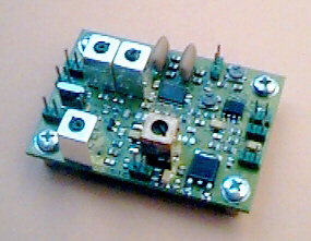
| SYMEK IFD-B-amplifier-mixer-demodulator board option 'IC970' | |
| 2x30cm thin coax cable, wire, shielded audio cable and hardware as needed. 100m H RF choke, 0.22m F. |
The IC970 can be modulated with 9600 Baud if the following modifications are made:
Open carefully the transceiver case and find the main circuit board. Locate the junction of diode D16 (black body with golden ring) and R52 toward the front center of the board and solder a 0.22 m F decoupling capacitor to this point. It would be a good idea to add a 100 m H choke in series to this capacitor to avoid influence of the oscillator RF to the modem.
At this point, the external modem (TNC Pin 1 - modulation) is connected via a shielded audio cable. Carefully adjust the signal level to obtain the correct deviation.
Check the manual for connecting the PTT to one of the auxiliary Connectors. Suited is ACC1 socket Pin 3 or DATA socket Pin 7. are already available as PTT connection for keying the transmitter.
 Open
the top cover of the transceiver (front towards you). Remove the speaker cable.
Remove the switching power supply (if present) together with the large panel and
the fan. (4 screws)
Open
the top cover of the transceiver (front towards you). Remove the speaker cable.
Remove the switching power supply (if present) together with the large panel and
the fan. (4 screws)
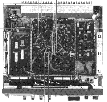
At the right side, you find the RF-B unit. Remove all coax connectors and all screws to access the solder side of this board. (see photo).
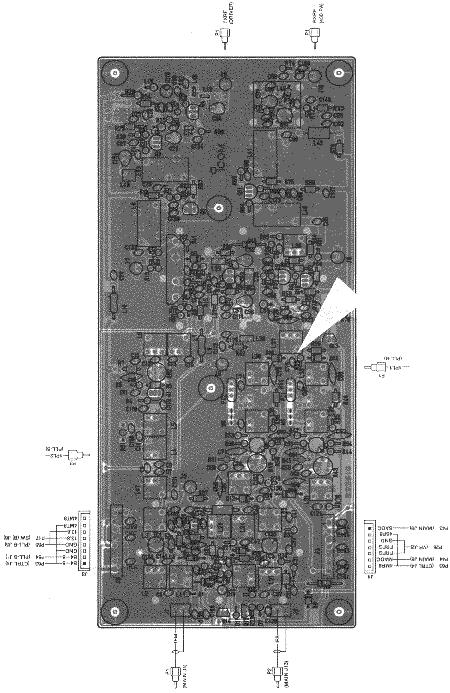 The RF-B unit is located at the right side, Top cover removedBottom view RF-B
board. The arrow shows the location of C76
The RF-B unit is located at the right side, Top cover removedBottom view RF-B
board. The arrow shows the location of C76
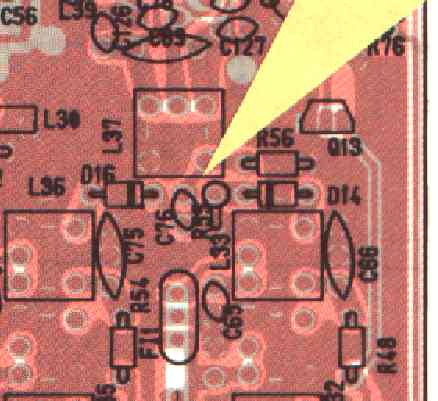 Magnified view to C76 capacitor
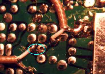 Remove coupling capacitor C76 (56pF) (shown as ellipse here) and solder the
center conductors of two thin coax cables (20-30 cm each) to the both solder
pads where C76 was connected before.
Remove coupling capacitor C76 (56pF) (shown as ellipse here) and solder the
center conductors of two thin coax cables (20-30 cm each) to the both solder
pads where C76 was connected before.
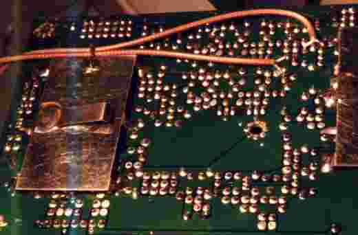 Bottom view of the board with the two coax cables soldered.
![]() Schematic diagram showing the mixer
(right) and the filter (left) coupled with C76 (red arrow)
Schematic diagram showing the mixer
(right) and the filter (left) coupled with C76 (red arrow)
The 'mixer' cable leading to the mixer shows a very low resistance (ohmmeter) of 2-5 Ohm to ground. Measuring the 'filter' cable leading to the xtal-filters via two switching diodes shows approx. 2 kOhms.
 In the compartment, where the RF-B unit is installed, there is enough space to
install the IFD. We installed it parallel to the front panel. Check if the
panel, supporting the power supply, fits after haveing installed the IFD. You
may use one of the screws of the oscillator unit (front right behind the front
panel) and replaxe it by a short hex nut spacer. You should solder all
connections before:
In the compartment, where the RF-B unit is installed, there is enough space to
install the IFD. We installed it parallel to the front panel. Check if the
panel, supporting the power supply, fits after haveing installed the IFD. You
may use one of the screws of the oscillator unit (front right behind the front
panel) and replaxe it by a short hex nut spacer. You should solder all
connections before:
1. solder the coax cable "mixer" to the RF-IN (terminal M1) (shield to M2)
2. solder the coax cable "filter" to the RF-OUT (terminal M11) (shield to M12)
3. solder a 50 cm red wire to a terminal with permanent +12V, e.g. directly to the 12V main power supply switch.
4. The demodulator output (terminal M63, data out) goes via a shielded cable to the input of a TNC (transceiver's demodulator output).
5. Ground connection for power supply is not necessary (cable shields are already grounded).
At the rear panel, there are some spare holes which can be used to feed-thru the cables or to install additional connectors for the high-speed data reception.
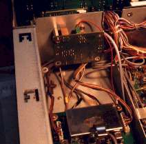
top of IC970 (rear view) with RF-B board (lower) and IFD (center)
You need a 3 wire + screen cable from the IC970 to the packet controller.
Ground (connect to TNC pin 2 GND
PTT (connect to TNC pin 3: PTT)
Modulation (connect to TNC pin 1: Mod)
data output (connect to TNC pin 4: Demod)
Before reinstalling all covers, check if the transceiver works exactly as before. Apply a 1 to 10 microvolt signal and check S-meter reading. Because of the additional IF amplifier, the s-meter may show few dB difference.
Adjust the output level of the TNC to get the desired frequency deviation / modulation index. Do not overmodulate as the transceiver will totally switch off the modulator. The modulator should work perfectly for all FSK baudrates from 9600 to 19200 baud. Note: the input voltage determines the bandwidth of the transmit signal. You will need more signal amplitude for higher baudrates.
The RSSI output should be near zero volts (<0.1 m V signal) and go up to 4 volts (1 mV rf input)
When receiving a 19200, 38400 or 76800 baud signal, there will be a perfect eye at the data output. The output voltage at 38400 Baud is typically 0.5 volt pp.
Testing the sensitivity, a sample IC970 showed S9 at -99 dBm signal before inserting the IFD and 2 dB more gain (-101 dBm) with the IFD built-in. Identical values at main and sub band.