Ulf Kumm, DK9SJ, edited by James Miller, G3RUH
Uplink (TX): any frequency (144-145 MHz, 430-440 MHz etc.), FSK-modulation
4800 up to 76800 kBaud,
Downlink (RX): 430-440 MHz, 38400/76800 Baud FSK (153 kBaud with wider filters
(optional)).
Material required:
| SYMEK IFD-B-amplifier-mixer-demodulator board option 'FT736', including: 100 kW 1/20 watt resistor, 2.2 nF ceramic disc capacitor, 30 cm thin coax cable | |
| wire and other hardware, connectors, heatshrink tube and other parts as needed. |
1. Transmitter (modulation):
Open the top cover of the transceiver (front towards you); take care of the speaker cable!
(Picture of FT736, cover removed)
The board on the left is the transmitter unit. Find the 45x30 mm open screening frame on it.
It contains the 13 MHz PLL, which will be modulated by the 9600 baud FSK signalThe modulation signal is applied to the varactor diode DO1 (the left one in the schematics). You will find two grey coloured plastic diodes with a orange dot at the cathode side in the screened box. DO2 is near to the transceiver's front with the dot oriented to the rear and DO1 is in the middle of the box, dot (=cathode) oriented to the left. Now carefully solder a 100 k
W resistor to the cathode pin of this varactor diode. Use a 1/20 watt resistor with thin wires.From the other end of the resistor, solder a 2.2 nF ceramic disc capacitor to ground. The capacitor may be soldered directly to the screening box. The joint of 100 k
W and 2.2 nF is the new modulator input.2. PTT (transmitter keying):
Open the top cover of the transceiver (front towards you) Parallel to the
front side is the large control unit board. Exactly in the middle (50mm behind
the 'PROC' lamp) there is a white 12 pin connector J13 between the components
DO9 and C14. The connector is numbered from pin1 right (near C14) to pin 12
(near DO9).
Pin 3 of J13 is the PTT connection for keying the transmitter. Solder a
very long wire to the solder pad on the circuit board or the white wire leaving
the connector pin 3. Pass the wire parallel to the other wires. Do not cross the
sharp edge because the wire could be pinched later when the top cover is
replaced.
3. Demodulator output:
Open the top cover of the transceiver (front towards you). At the right rear
side is the '430 MHz front unit' box (60x20x20 mm). The only visible connections
to this box are two grey coax cables. One of them is 10 cm long and goes across
the large 430 MHz RF unit (right side) to the 'RXLOCAL' point. The shorter one
goes to a point on the RF unit marked with 'IN'.
Now carefully cut the short coax cable 3 cm from the end, where it plugs into
the 435 MHz rear unit! Then this shorter piece can be unplugged and the splice
easily made outside of the radio. This leaves a longer piece of connected coax
inside the radio, which is easier to splice, since this piece cannot be removed
easily for splicing. Remove the insulation on both ends of the cable. You will
have to splice a extension cable to both ends later.
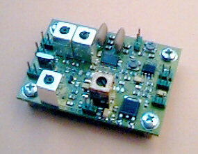
The IFD demodulator board may be mounted anywhere in the FT736, the best place would be at the rear side (bottom) where there is space left for an additional 50 MHz unit. The tiny IFD-board may be attached to the rear panel (heatsink) with a 20 mm spacer or mounted to the bottom plate using adhesive spacers or whatever you like. When using adhesives, keep in mind that the transceiver gets hot.
Wiring: use thin 50
W PTFE insulated coax cables. Extend the cable going into the 430 MHz front unit box and connect it to the RF-IN of IFD. Extend the cable going to the 'IN' point of the 430 MHz RF unit board and connect it to the RF-OUT of IFD. Note: connections on the IFD-board all have two pins: the one near the edge is the signal pin, the adjacent pin towards the center of the board is ground. You must solder both signal and ground of the cables. Use heatshrink tube for insulation.(Component location plan of IFD board, showing where to connect the signals)
The cut coax cable was also used for supply 9 volt dc power to the 430 MHz front unit. The IFD contains RF-chokes to maintain the DC supply as it was before cutting the cable. Moreover the IFD will be supplied via the coax as well, so here is no need to solder any supply voltage cables to the IFD.
4
. Connection of the packet-radio-controller (TNC):You need a 3 wire + screen cable from the FT736 to the packet controller. Try to fix a 5 pin DIN socket anywhere at the FT736 rear side. A simple solution would be to feed a short cable with a 5 pin female connector through the rear panel of the radio and extend it with a standard 5 pin male to 5 pin male standard keyboard or stereo cable. A compatible 7 or 8 pin connector can be used as well, the spare pins may be used for RSSI or AFC etc. later.
Modulation: with most TNCs, pin 1 'MIC-MOD' is used as modulation output. Connect this pin to the joint of the 100 k
W resistor and the 2.2 nF capacitor in the PLL box. Use shielded cable.Demodulator: with most TNCs, pin 4 'SPK-DEMOD' is used as analog data input. Connect this pin to the 'DATA OUT' pin on the IFD demodulator board. Use shielded cable.
PTT: with most TNCs, pin 3 'PTT' is used as PTT switch output. Connect this pin to the J13 connector on Control Unit.
Ground: (TNC pin 2) use any ground connection or use the shields of the cables.
RSSI: if you like, the RSSI output of the IFD may be connected to pin 5 (or 6, 7, 8 if available)
5
. Setup and test:After reinstalling all FT736 covers, the transceiver should work exactly as before. Because of the additional IF amplifier, the S-meter may show few dB increase.
Adjust the output level of the TNC to get the desired frequency deviation / modulation index. The modulator should work perfectly for all FSK baudrates from 9600 to 76800 baud. Note: the input voltage determines the bandwidth of the transmit signal. A 76 kbaud signal has 8 times more bandwidth, hence you will need more signal amplitude for higher baudrates.
The RSSI output should be near zero volts (<0.1
m V signal) and go up to 4 volts (1 mV rf input)When receiving a 19200, 38400 or 76800 baud signal, there will be a perfect eye at the data output. The output voltage at 38400 Baud is typically 0.5 volt pp.
For 9600 baud, a peak-to-peak input voltage of 0.5 volt is typical.
6
. Questions and Answers:Q: why is the IF signal fed through the IFD? Wouldn't it be easier to connect
the IFD in parallel to the mixer output?
A: directly after the coax cable between mixer and RF unit, the signal passes a
quartz filter. As with every filter, the input impedance varies significantly
with frequency: within the passband, the filter is matched, outside the
passband, the filter reflects the signal. The amplitude spectrum at the filter
input shows a sharp notch at the passband. Attaching a parallel demodulator here
would cause severe distortions due to the varying load. So, the signal after the
mixer has to be buffered. The amplified signal is attenuated again to get the
same (or a few dB more) signal level as without amplifier.
Q: is a AFC output available?
A: There is an unconnected pair of pins on the printed circuit board (M60/M61). These pins can be connected to the joint of R52/C52 (DET out) via a 100 k
W resistor to pin M60. The voltage measured at this pin will depend on the center frequency of the received FM signal.Q: how do I decode a fast packet-radio signal of 38kBaud or more?
A: The TNC2 with the Z80 processor cannot decode signals beyond 19200 Baud. The newer TNC3 or TNC31 series is capable of receive and transmit baudrates up to 1 Mbit/s. There are modems with all common baudrates (9600, 19200, 38400, 76800, 153600 and above). Special modems with different RX and TX speed (e.g. TX 9600 / RX 38400 for UO-12) are also available. When using WISP software with a TNC3 packet controller, you may use the modem 2 for receiving and modem 1 for transmitting. As WISP uses kiss-mode, both modems are received simultaneously, the data will be transmitted via the default port 1.
(Picture: Schematics IFD-B)
With FT736, a 36.730 MHz quartz (fundamental mode) is used. The IF of FT736 is 10.7 MHz above (47.430 MHz)