out of production
Uplink (TX): any frequency (144-146 MHz, 430-440 MHz etc.), FSK-modulation 4800 up to 76800 kBaud,| SYMEK IFD-B-amplifier-mixer-demodulator board option 'TM 455' | |
| wire and other hardware, connectors, heatshrink tube and other parts as needed. |
The TM455 has a build-in capability to be used as 9600 baud FSK packet-radio
transmitter.
See the instruction manual of TM 455 Page 22.
Make sure, not to over-modulate the transmitter. Set the TNC output level according to instructions.
2. Demodulator output:It is very easy to install the IFD to TM455, as there exists a test pin where the IFD can be directly connected to. Here the schematics:
L410 has an output (TP401) to connect external
demodulators without problems.
Open both covers of the transceiver and find the TP401 test pin on TX-RX Unit.
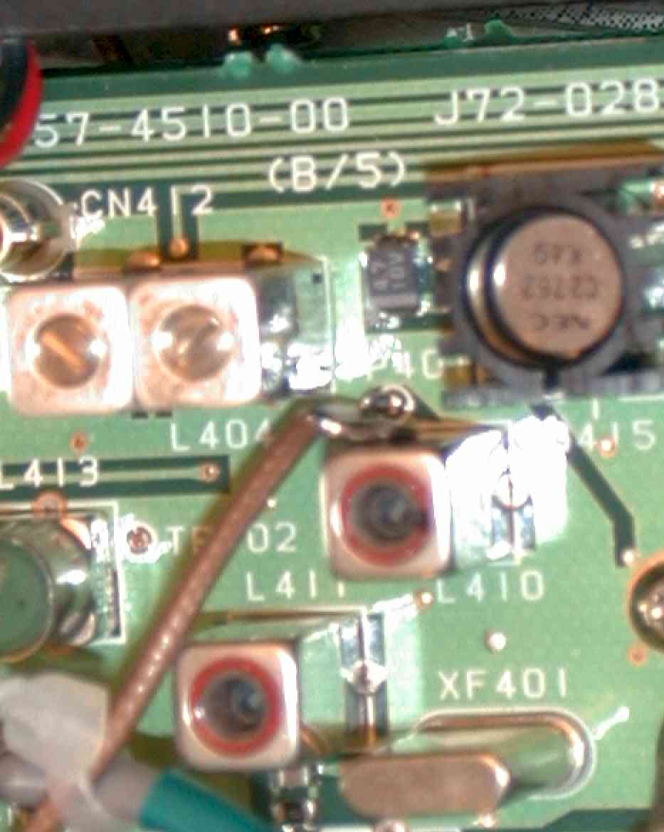
Carefully solder the inner conductor of a thin coax to TP401 and the shield to the filter can nearby.
Feed the cable through some hole in the chassis to the opposite side There, between fan and rear panel, you may install the IFD board upside down. Use a thin and flexible isolating material, as PE or PVC to prevent short circuits. The board should be placed close to the fan because of the form of the cover.
Tu prevent short circuits between bottom cover and IFD, use a flat, hard insulation material (plastic or polyacryl).
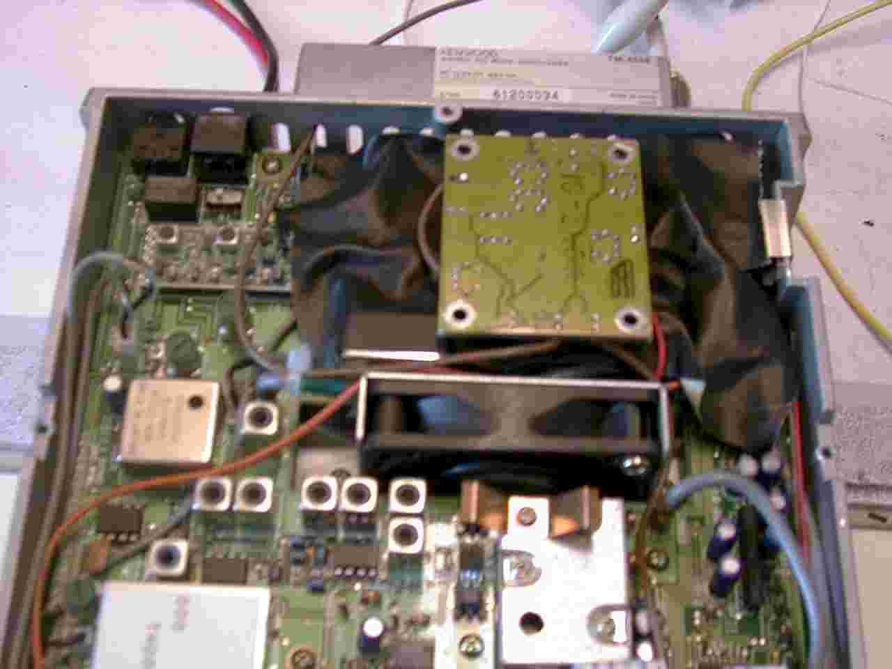
The coax comeing from TP 401 goes to IFD input (shield to IFD ground). IFD power-supply can be tapped at any point, where 12 volts are accessible. (see picture: red wire)
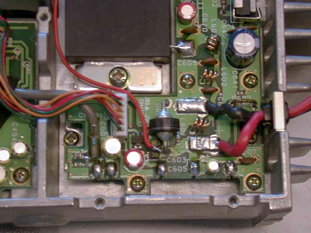
The data output of IFD is fed through one of the holes in rear panel and goes to the TNC data input.
Results: You can receive high speed FSK data signals without problems after this modification. Here the eye diagram of a 76800 Baud FSK signal, received with TM455 and IFD.
Ground connection for power supply is not necessary (cable shields are already grounded).
3. Setup and test:
After reinstalling all covers, the transceiver should work exactly as before. Adjust the output level of the TNC to get the desired frequency deviation / modulation index. Do not overmodulate. The RSSI output (if connected) should be near zero volts (<0.1 m V signal) and go up to 4 volts (1 mV rf input)
When receiving a 19200, 38400 or 76800 baud signal, there will be a perfect
eye at the data output.
The output voltage at 38400 Baud is typically 0.5 volt pp.
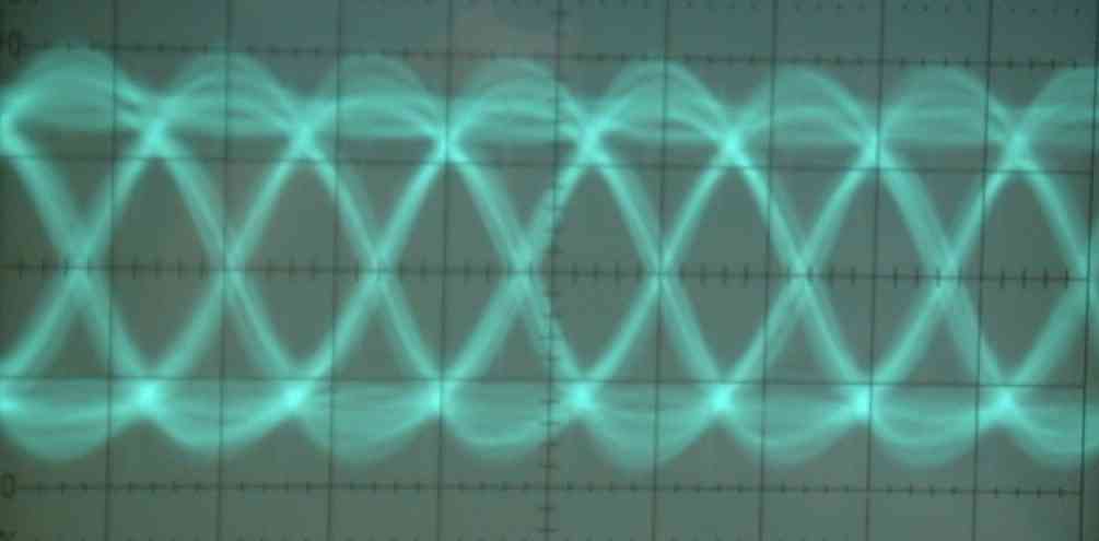
TM455 with IFD installed. Typical data output eye diagram of a 76800 baud modulated FSK signal.
4. Questions and Answers:
Q: is a AFC output available?
A: There is an unconnected pair of pins on the printed circuit board (M60/M61). These pins can be connected to the joint of R52/C52 (DET out) via a 100 kW resistor to pin M60. The voltage measured at this pin will depend on the center frequency of the received FM signal.
Q: how do I decode a fast packet-radio signal of 38kBaud or more?
A: The TNC2 with the Z80 processor cannot decode signals beyond 19200 Baud. The newer TNC3 or TNC31 series is capable of receive and transmit baudrates up to 1 Mbit/s. There are modems with all common baudrates (9600, 19200, 38400, 76800, 153600 and above). Special modems with different RX and TX speed (e.g. TX 9600 / RX 38400 for UO-12) are also available. When using WISP software with a TNC3 packet controller, you may use the modem 2 for receiving and modem 1 for transmitting. As WISP uses kiss-mode, both modems are received simultaneously, the data will be transmitted via the default port 1